A Simple Electronic-Type Gravity Meter
Abstract:
Gravity meters (also called gravimeters) are devices used to measure the relative acceleration of the force of gravity at some particular location. Present day gravimeters are mostly but very sensitive forms of spring-type scale systems in which changes in the weight o a fixed mass is measured. Such units are also very sensitive to other disturbances, e/g/., local vibrations. They are generally fabricated with complex suspension systems to avoid such problems and thus are very expensive. Described here, however, is a very simple low-cost electronic type gravimeter, which while very sensitive, is also relatively free from local disturbances such as vibrations. Thus it is a rugged portable-type unit which can be easily constructed by the average electronic experimenter. With its high sensitivity to ‘local’ variations in the gravity field, it could thus be used by the amateur prospector in search for oil and mineral deposits. Moreover, it could be used as an effective device (supplementary) by the professionals in this area.
Introduction:
The force of gravity is unique in that while it is a matter of common everyday experience for most people, it also remains as quite an enigma with respect to its true nature. The average person is well aware that the force of the Earth’s gravity is reflected in the mass of an object, i.e., if one has more body mass, one is ‘heavier’, and that such ‘heaviness’ can be measured by scale systems. However, just how such gravity fields interact with mass has been a mystery to mankind ever since man first realized that all objects ‘fell’. Moreover, it remains a mystery to most scientists even to this day, although many theories have been advanced to explain the effect.
While the true nature of gravity is as yet unclear, it will be considered as a ‘force field’ for the purposes of this article. The nature of this force field has been considered by the author in many other presentations, including two papers published by this very magazine [Radio-Electronics] (Ref. 1,2). However, here we will be concerned mainly with the earth’s gravitational field, how we can measure it, and how we can use these measurements in specific applications. We will do this with devices which may be called gravity meters, or gravimeters.
Basic Gravimeters:
On earth, the unimpeded downward motion of a mass in the earth’s gravitational field is called the acceleration of free fall, or g, and it is in the order of 32 feet per second squared (or 980 centimeters per second squared). This value of g varies slightly with the earth latitudes and distances from the earth’s center. It is also known that g is affected by local mass anomalies such as light or heavy mineral deposits, or the presence (laterally) of dense rocks, such as may be found in nearby mountains. The value of g at a particular location has been most accurately determined from the oscillation period of a pendulum. However, reasonable accurate determinations may be made wit the use of sensitive spring-type scales which can determine small changes in the ‘weight’ of a fixed mass.
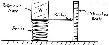
In the simple spring-type scale system, the downward acceleration of a mass (as imparted by gravity) is impeded or retarded by the restoring force presented by the spring as shown in Figure (1a). Here, the change in the position of the mass is shown by a pointer and a calibrated scale. The pointer position is generally amplified by a lever or system of levers. For an accurate small weight variation determination the scale system must have a linear response to the weight variations, i.e., the system must obey Hooke’s Law, that is the restoring force constant must also be linear. In this case, the relationship that the weight would be equal to the mass times the accelerating factor, i.e., W = mg, holds, since the mass is held constant, any change in weight would imply a change in g. Rather than the purely mechanical type of readout for weight variations, an electrical type of readout is preferred. The author has previously developed a very simple mechanical-type of gravimeter with an electrical readout as shown in Figure (1b)(Ref. 3). Here, the restoring force in the scale system was provided by a conductive foam material in which resistance changes due to weight variations were read directly by an ohmmeter which could be calibrated in terms of weight instead of resistance.
Based upon the above principles, many types of mechanical gravity meters can be designed. Such mechanical systems are quite sensitive since the earth’s gravity field interacts with the great many atoms (ions) to be founding the mass of the reference weight. For example, in the author’s test of the system shown in Figure (1b), the unit responded noticeably to the movements of a person located directly two floors above the location of this test unit. However, such devices are also highly susceptible to other disturbances such as vibrations, air currents, or temperature differentials. For an effective gravimeter based on mechanical methods, the system must be guarded against these unwanted effects, or compensated for such effects, and thus such systems are quite complex and thus expensive. Also unrecognized by most designers of such systems are the effects of cosmic gravity ‘events’ on such gravimeters (as described in Refs 1, 2 , and 3). Such cosmic effects may be circumvented to some extent in gravimeters which balance one mass against another (the typical old-fashioned balance scale), but the vibration, air current, and temperature problems would still remain. A more practical solution to these problems will be given by the electronic-type gravimeter as developed by the author.
Electronic Gravimeter Basics:
This electronic gravimeter is intended specifically for the measurement of the averaged earth gravitational field, i.e., the acceleration factor, g. It is but a special modification of the author’s basic gravity detection devices, which are adequately described in References 1-5, and thus will not be further considered here except in respect to their use in earth gravity measurements.
The gravity detectors respond to both a dynamic (AC) gravity component, due to variable terrestrial and cosmic events, as well as an averaged (DC) gravity component, which largely reflects the earth’s gravitational field, i.e., the acceleration factor, g. In order to emphasize this DC component the detector sections, IC1, is made high in sensitivity (but adjustable), and the output is further amplified in the amplifier section, IC2. Moreover, in order to further emphasize the DC component only, the output is heavily filtered in order to minimize the AC components as much as feasible. It may not be possible to remove all AC components in this process, since there exists in the cosmic radiation some very-large-amplitude but very-low frequency components. However, the averaged earth gravitational field (as detected here) can be made sufficiently stabilized so that the unit will now respond with sufficient sensitivity to the more local gravity field ‘modulations’ due to factors as either the presence of dense man-made masses in line with the earth’s gravity field, or the presence of hidden mass anomalies in the earth’s structure which are also in line with the earth’s gravity field. Thus this unit will serve many of the ordinary purposes of a gravimeter device. But most important here, the electronic gravimeter will be found to be insensitive to local vibrations, air currents, temperature variations, and acoustical or electrical noises, and thus respond only to the effects of a gravity field itself. Thus it will be useful in many areas of scientific research and technology. Most of all, it is a simple device and very low in cost, and thus within the reach and capabilities of researchers, scientists, and technologists, both the amateur and the professional.
Practical Electronic Gravimeter:
A typical electronic gravimeter circuit is given in Figure (2). Since the unit was intended for portable use and long battery life, it was constructed around a CMOS type operational amplifier, the Intersil type ICL7621. That device works very well with a +/- 1.5 volt battery supply and is also fairly insensitive to RF fields due to the presence of input diode protection. Also the very high input resistance for this device enables the use of a smaller value gravity sensing input capacitor, C1, which will still keep any possible input resonances at 1 Hz or lower.
The sensitivity of the detector is controlled mainly by the feedback resistance, R1. While the unit normally uses the full gain of 100 times of the amplifier stage, IC2, some gain control, R2, is used to calibrate the unit or just to set the output meter, M, to a particular point on the scale.
Three levels of output integration in the output filter are provided by the selector switch, SW2, which was made of the shorting type in order to progressively sum the capacitors in the filter unit. This was done in order to conserve capacitor space in the portable unit. However, the researcher or experimenter may add additional capacitance, if desired, by means of the output jack, J1. This jack is normally used to provide an output to an external meter device or some recording unit, such as a strip chart recorder or a computer.
The self-contained voltmeter, M, is used to visually monitor the averaged gravity field, i.e., the g factor, in terms of an output voltage. With the use of the calibration control, R2, the averaged gravity response can be adjusted over the range of about 500 to 700 millivolts. Therefore, the full range scale of this meter circuit was made one volt.
The prototype unit was constructed in a 5 x 3 x 2 inch aluminum box as shown in Figure (3), with its own self-contained battery supply. However, the experimenter has much leeway in the construction of this unit. None of the components are critical in value. Another equivalent type CMOS type operational amplifier could be used as well. A bipolar op-amp could also be used, but here, the input sensing capacitor, C1, would have to be increased to at least 1000 uF and the battery supply voltage increased to at least +/- 4.5 volts. Some adjustment in the voltmeter range will also be required.
Applications:
While the sensitivity control, R1, in the detector stage, IC1, is adjustable, it is normally used full sensitivity, i.e., 5 megaohms, for most applications. The calibration control, R2, is normally set for nominal output of 600 millivolts (or 30 on the author’s 0-50 uA meter scale). It must be remembered that due to the very long time constant of the output filter, any changes made with the circuitry controls will take a long time to stabilize. So don’t try changing control positions in the middle of any measurement! The fastest time (integration) for the output filter will be in position #1 of the filter switch, SW2. Progressively longer integration times will be seen in positions #2 and #3.
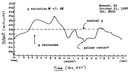
It may be better to keep the filter in position #3 for most earth gravitational field experiments. Shown in Figure (4) is a typical 24-hour response in the earth’s gravity field as detected with this unit. It will be noticed that there is a 12-hour variation in the response at times, and most of the variation and some ‘structure’ may be related to some possible ‘super’ black holes located in the ‘center’ of our universe (See Ref. 3).
For a response to the more ‘local’ gravity anomalies, the filter response may be better set to positions #1 or #2. With the proper adjustment of the gravimeter sensitivity, gain and filter response, it should be possible to ‘observe’ the transit o local dense masses which are in line with the detector and the earth gravity field. These are actually ‘shadows’ of the objects, very much like an opaque object casting an optical shadow. An application of this which came to the author’s mind was the possible use of such a detector by a submarine to locate the presence of a surface vessel directly above it.
A major application of the electronic gravimeter, of course, is its use in the location of large underground mass anomalies, which could indicate the possible presence of oil or mineral deposits. Here, both the amateur and the professional prospector may wish to try the device in such an application. This is presently beyond the attempts on the part of the author.
Less well known to most scientists, either amateur or professional, is the fact that severe effects in the earth gravity field can affect the earth’s weather. This will be because changes in the earth gravity components can affect the jet stream patterns which largely control our weather patterns. The author believes that such noticeable gravitational disturbances did indeed occur in December 1986 and in March 1988, and these indeed did affect our weather patterns. The earth has experienced severe weather changes in this time period!
Conclusions:
A basic electronic gravimeter device, which could supplement the existing gravimeter devices has been described briefly here. The further development of this device could have much impact on future earth gravity research. Its simplicity and low cost should enable both the amateur and professional researchers, as well as technologists, to enter into this particular aspect of gravity field research.
References:
1) Hodowanec, G.: “All About Gravitaitonal Waves”; Radio-Electronics, April 1986.
2) Hodowanec, G.: “All About Gravitaional Impulses”; Radio-Electronics Electronic Experimenters Handbook, January 1989.
3) Hodowanec, G.: “Simple gravimeter Detects Gravity ‘Shadow’ Signals; Tesla ’86, vol. 2 (#2), March-April 1986.
4) Hodowanec, G.: Rhysmonic Cosmology.
Parts List:
Typical Electronic Gravimeter
All resistors are 1/4 W, 5%
R1 5 megaohm, potentiometer
R2 2k ohms, potentiometer
R3, R4 4.7k ohms
R5 470k ohms
R6 1k ohms
R7 20k ohms
Capacitors
C1 220 uF, 10 volts, electrolytic
C2 2200 uF, 10 volts, electrolytic
C3, C4 9400 uF, 10 volts, electrolytic
Miscellaneous
J1 phone jack (open circuit)
SW1 DPST miniature switch
SW2 3-pole rotary switch (shorting type)
IC1, IC2 ICL7621 (Intersil) op-amp
M 50 uA meter movement
Figure (1): Basic Spring-type Gravimeters ~
(1a): Mechanical Readout ~
(1b): Electrical Readout ~
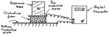
Figure (2): Typical Electronic Gravimeter ~
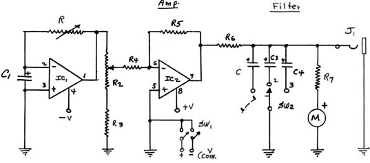
Figure (3): Prototype Electronic Gravimeter ~
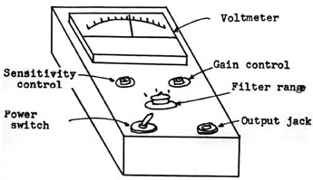
Figure (4) Typical diurnal variation of the earth’s gravity flux as measured with the electronic gravimeter ~
