5-20-2005
A. Background
When McClain and Wooten announced their MRA in January 1995, I tried to duplicate their work with a small red pulse transformer marked 5mH (5:1) ratio. The original test results were reported in a Cosmology Note (1-30-95). I used the transformer then in a step-down mode since the series-resonant primary winding would be Q-multiplied to much higher voltages which then would be Q-multiplied to much higher voltages which then could be stepped down for much higher DC output currents. This worked out quite well in a self-sustaining mode of operation and I released much material on this to you over the years.
However, I was also interested in a stand-alone mode of operation where a local source of operating energy would not be needed! This mode would probably need more output voltage. On 4-3-95, I briefly looked at the step-up mode of operation for this same transformer. To save time, I did not try to determine an optimum frequency for series resonance but decided to directly drive the primary (now 1 MH) with my tube-type signal generator (Range: 10 Hz - 210 KHz). I was surprised at the results! The input-drive level appeared to start at about 0.2 V (RMS) at 80 KHz and drop down with an increase in frequency to about 10 mV (RMS) at 200 KHz! The input power needed at 200 KHz appeared to be only in the order of 0.001 mW! The rectified DC output went down from about 2.5 at 80 KHz to about 8 V at 210 KHz! The test seemed to peak at about 186 KHz (a rhysmonic resonance frequency) with about 8.2 V DC at 0.55 mA for an output of about 4.5 mW. Thus power gain appeared to be quite high, at least 1000 (plus?) times! I sent the rough data to McClain and Wootan saying, “This test was trying to tell us something”, but I don’t know if they every checked it out.
B. A More Recent Test
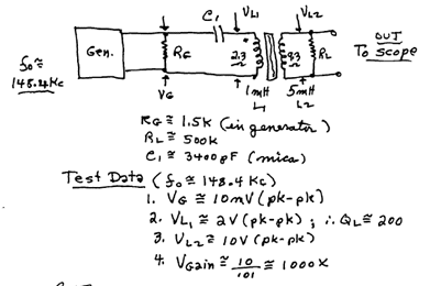
The 1995 test was performed with ordinary analog and digital meters since I did not have a decent oscilloscope at that time. I recently decided to look at this test again using a 20 MHz oscilloscope. The initial simple test is given below (after I determined the optimum rhysmonic resonant frequency to be about 148.4 KHz!) (Figure 1).
Figure 1

C. Test Remarks
With the 20 MHz scope measurements, VG would start at about 1.5 V (pk-pk) and then sharply drop to about 10 mV at the resonant frequency of 148.4 KHz ad then return to 1.5 V (pk-pk). This verified the high loaded Q of 200 ! Thus VL was Q-multiplied! The VL2 voltage was simply transformer raised to 10 V. The power gains noted here should also have been in the order of 100 Q (plus) times.
D. Conclusions
1. I recently received a pair of currently made miniature pulse transformers made by Tamura. They are rated at 2 mH at a 2:1 ratio. These may be more suitable for exploratory tests, even at so-called flea powers.
2. The Tamura transformers will be tested for resonant frequencies and normal step-up and step-down operations.
3. The final test will be in a novel circuit where the optimum performance in (2) above will be tested with special feedback techniques intended to keep oscillator resonant frequency more or less constant. This will ensure that the stand-alone will draw the maximum energy from the G-fields and thus sustain operation (no local supply needed).